August, 2025
EMS An Environment Management System
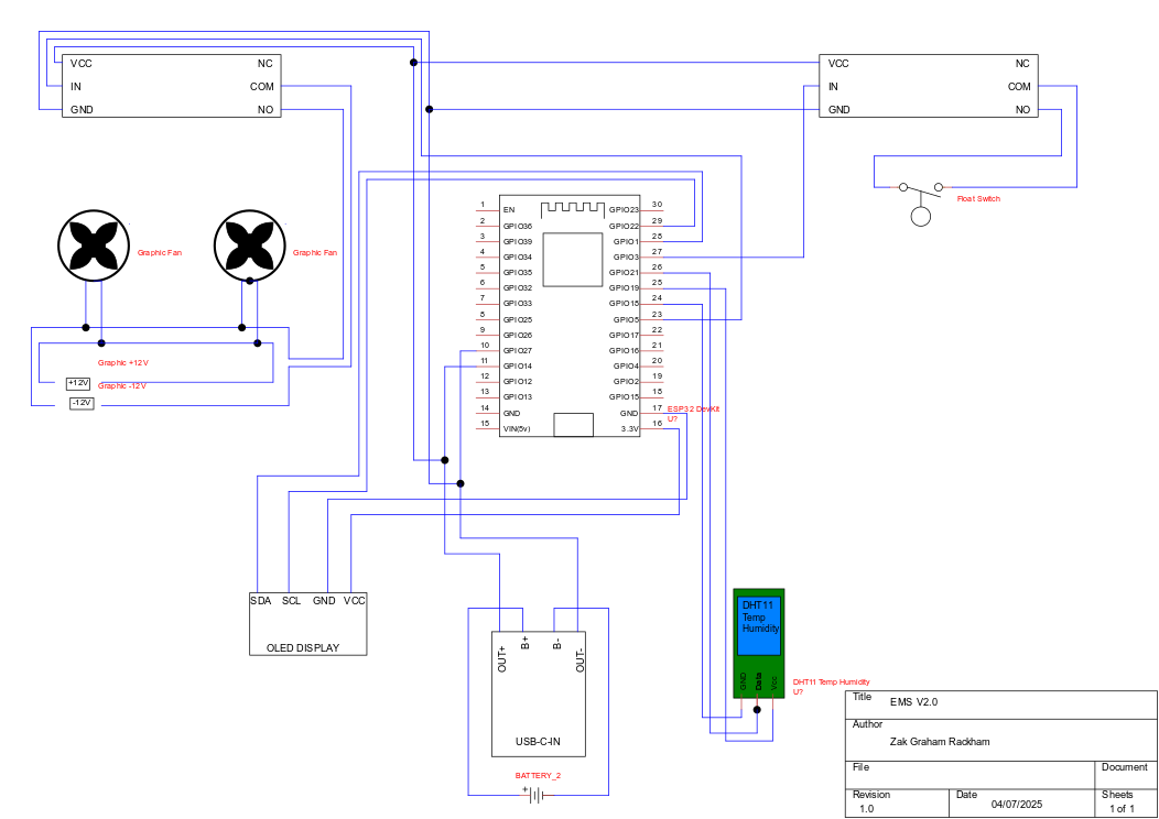
This project applies an Environmental Management System (EMS)
concept as a Terrarium Management System designed specifically
for a crested gecko habitat. The system regulates key environmental
factors such as temperature and humidity, using an ultrasonic
atomiser to maintain proper humidity levels and a set of fans
to provide cooling when needed. Control and automation are managed
through a NodeMCU v3.0 microcontroller paired with relays, while MQTT
protocol handles network communications, enabling remote monitoring
and control. The unit is powered by two 18650 lithium-ion batteries
wired in parallel, providing a stable and efficient power supply
for continuous habitat regulation.
Arduino Code for Node MCU
The code runs on an ESP8266 and uses a DHT11 sensor to measure temperature and humidity,
displaying values on an OLED screen. It connects to Wi-Fi and communicates with an MQTT
broker to publish sensor readings and receive commands. Relays control a fan and humidifier,
which can run automatically based on sensor thresholds or manually through MQTT messages.
The main loop cycles through reading the sensor, updating the display, publishing data,
and managing MQTT connections.
/*
* @file ESP8266 Environment Management System
* @brief Client system for EMS
* @author Zak G Rackham
* Contact: zak.g.rackham@gmail.com
*/
#include
#include
#include
#include
#include
#include
#include
#define SCREEN_WIDTH 128 // OLED display width, in pixels
#define SCREEN_HEIGHT 64 // OLED display height, in pixels
// Declaration for an SSD1306 display connected to I2C (SDA, SCL pins)
// The pins for I2C are defined by the Wire-library.
// On an arduino UNO: A4(SDA), A5(SCL)
// On an arduino MEGA 2560: 20(SDA), 21(SCL)
// On an arduino LEONARDO: 2(SDA), 3(SCL), ...
#define OLED_RESET -1 // Reset pin # (or -1 if sharing Arduino reset pin)
#define SCREEN_ADDRESS 0x3C ///< See datasheet for Address; 0x3D for 128x64, 0x3C for 128x32
Adafruit_SSD1306 display(SCREEN_WIDTH, SCREEN_HEIGHT, &Wire, OLED_RESET);
#define WIFI_NAME "SSID"
#define WIFI_PASSWORD "PASSWORD"
WiFiClient espClient;
PubSubClient client;
unsigned long lastMsg = 0;
unsigned long lastMsg1 = 0;
#define MSG_BUFFER_SIZE (50)
char msg[MSG_BUFFER_SIZE];
char msg1[MSG_BUFFER_SIZE];
int value = 0;
int temperature = 0;
int humidity = 0;
int count = 0;
// Create an instance of the DHT11 class.
// - For Arduino: Connect the sensor to Digital I/O Pin 2.
// - For ESP32: Connect the sensor to pin GPIO2 or P2.
// - For ESP8266: Connect the sensor to GPIO2 or D4.
DHT11 dht11(2);
int fansys = 14;
bool fanstate = false;
bool humidifierstate = false;
void setup() {
pinMode(2, OUTPUT); // Initialize the LED_BUILTIN pin as an output
pinMode(14, OUTPUT); // Initialise the RELAY_TRIGGER pin as an output
pinMode(0, OUTPUT); // Initialise the RELAY_TRIGGER pin as an output
Serial.begin(9600);
// SSD1306_SWITCHCAPVCC = generate display voltage from 3.3V internally
if(!display.begin(SSD1306_SWITCHCAPVCC, SCREEN_ADDRESS)) {
Serial.println(F("SSD1306 allocation failed"));
}
// Show initial display buffer contents on the screen --
// the library initializes this with an Adafruit splash screen.
display.display();
delay(2000); // Pause for 2 seconds
// Clear the buffer
display.clearDisplay();
// Draw a single pixel in white
display.drawPixel(10, 10, SSD1306_WHITE);
// Show the display buffer on the screen. You MUST call display() after
// drawing commands to make them visible on screen!
display.display();
delay(2000);
// display.display() is NOT necessary after every single drawing command,
// unless that's what you want...rather, you can batch up a bunch of
// drawing operations and then update the screen all at once by calling
// display.display(). These examples demonstrate both approaches...
//testdrawrect(); // Draw rectangles (outlines)
WiFi.begin(WIFI_NAME, WIFI_PASSWORD);
Serial.print("Connecting");
while (WiFi.status() != WL_CONNECTED)
{
delay(500);
Serial.print(".");
}
Serial.println();
Serial.print("Connected, IP address: ");
Serial.println(WiFi.localIP());
//Setup the pubsub client connection
client.setClient(espClient);
client.setServer(SERVER IP,1883);
client.setCallback(callback);
// client is now configured for use
updatetext(); //Boot info screen
}
void callback(char* topic, byte* payload, unsigned int length) {
Serial.print("Message arrived [");
Serial.print(topic);
Serial.print("] ");
for (int i = 0; i < length; i++) {
Serial.print((char)payload[i]);
}
Serial.println();
// Switch on the LED if an 1 was received as first character
if ((char)payload[0] == '1') {
Serial.print("Message arrived = 1");
fanstate = true;
}
// Switch on the LED if an 1 was received as first character
if ((char)payload[0] == '0') {
Serial.print("Message arrived = 0");
fanstate = false;
}
if ((char)payload[0] == '2') {
Serial.print("Message arrived = 2");
humidifierstate = true;
}
if ((char)payload[0] == '3') {
Serial.print("Message arrived = 3");
humidifierstate = false;
}
}
void reconnect() {
// Loop until we're reconnected
while (!client.connected()) {
Serial.print("Attempting MQTT connection...");
// Create a random client ID
String clientId = "ESP8266Client-";
clientId += String(random(0xffff), HEX);
yield();
// Attempt to connect
if (client.connect(clientId.c_str())) {
Serial.println("connected");
yield();
// Once connected, publish an announcement...
client.publish("outTopic", "EMS Online");
// ... and resubscribe
client.subscribe("inTopic");
client.subscribe("emsSetFan", 0);
client.subscribe("emsSetHumidifier", 0);
} else {
Serial.print("failed, rc=");
Serial.print(client.state());
Serial.println(" try again on next execution");
// Wait 5 seconds before retrying
delay(1000);
break;
}
}
}
void testdrawrect(void) {
display.clearDisplay();
for(int16_t i=0; i 2000) {
lastMsg = now;
++value;
snprintf (msg, MSG_BUFFER_SIZE, "%ld", temperature);
Serial.print("Publish message: ");
Serial.println(msg);
client.publish("emsTemperature", msg);
}
}
void publishhum() {
unsigned long now1 = millis();
if (now1 - lastMsg1 > 2000) {
lastMsg1 = now1;
++value;
snprintf (msg1, MSG_BUFFER_SIZE, "%ld", humidity);
Serial.print("Publish message: ");
Serial.println(msg1);
client.publish("emsHumidity", msg1);
}
}
// the loop function runs over and over again forever
void loop() {
++count;
switch (count) {
case 1:
readdht();
updatedht11display();
break;
case 2:
client.loop();
yield();
break;
case 3:
publishtemp();
break;
case 4:
publishhum();
break;
case 5:
if (!client.connected()) {
reconnect();
}
count = 0;
break;
}
if (!fanstate){
//Turn on cooling auto
if (temperature > 25 && humidity > 50){
digitalWrite(14, HIGH);
}
else {
digitalWrite(14, LOW);
}
} else {
//Turn on cooling manual
digitalWrite(14, HIGH);
}
if (!humidifierstate){
//Turn on cooling auto
if (humidity < 50){
digitalWrite(0, HIGH);
}
else {
digitalWrite(0, LOW);
}
} else {
//Turn on cooling manual
digitalWrite(0, HIGH);
}
yield();
}Enclosure
The custom 3D-printed enclosure is designed in six sections to securely house the terrarium
management electronics. One section contains two 18650 lithium-ion batteries wired in parallel,
providing a combined capacity of around 5200 mAh at 3.7 V with a maximum continuous discharge
of approximately 20 A, ensuring stable and reliable power delivery. Another section holds
the OLED display and NodeMCU v3.0, allowing for both local monitoring and control.
The remaining four sections are dedicated to housing the relays, keeping the layout
compact, organized, and easy to service.